FR-A800 Plus Series
Easy startup and adjustment 
Parameters can be used for mechanical adjustment according to applications, useful for the startup and adjustment work of the system.
Setting and adjusting multiple devices including controllers were required for dancer control, and it took much time to start up the system.

There was a worry about the compatibility with the existing system.


![]()
- ● Complex position control of the dancer roll can be achieved by the inverter alone by setting parameters.
- ● By setting mechanical specifications, optimum control can be performed according to the system and the application.
- ● Analog/pulse signal input method is selectable at the discretion of the customer. Input via communication is also available.
- ● PID control enables and simplifies complex control using only the inverter.
- ● Automatic tension PI gain adjustment enables easy startup. (Tension PI gain tuning)

Example of startup procedure
The following procedure shows the parameter setting example for the dancer feedback speed control.

Perform setting according to the motor type and the control method.

Set the value for each parameter according to the control method and the motor type.
(Speed control gain adjustment or offline auto tuning is required according to the control method.)

*2: Setting is required for a motor other than a Mitsubishi Electric motor
(the SF-PR, SF-JR, SF-HR, SF-JRCA, SF-HRCA, or SF-V5RU (1500 r/min series) motor).

Set the mechanical specifications.

Set the mechanical specifications according to application.

By calculating the winding diameter of the winding/unwinding shaft, the tension is always optimized even if it changes along with the winding diameter change.


Select the input method and the input terminal function for the line speed command.
![]()
The line speed command input method can be selected from the following: analog input through a terminal (2, 4, 1, 6, etc.), single-phase pulse train input, encoder pulse input, and input via communication (CC-Link IE Field Network communication, DeviceNet™, PROFIBUS-DPV0, etc.).
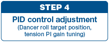
Set parameters to control the dancer roll and adjust the tension PI gain.

Set the target position, upper limit, and lower limit values for the dancer roll.

The PI gain is automatically adjusted by tension PI gain tuning. The time required for gain adjustment can be reduced.

![]()
Turn ON the X114 signal for using dancer feedback speed control and the winding diameter calculation function.